June 2012
| |
|
June 2012 |
Los Angeles Expo Line Finally Opens! April 28th was the opening day of the long-awaited Expo Line in Los Angeles. This would be the first rapid transit to the west side of Los Angeles since the Red Cars of the Pacific Electric stopping running in 1950. Shown in the first photo is one of the Siemens-built trains breaking the "first-train" barrier.
Of course the line was years behind schedule as almost every line opening in the City of the Angels due to the fact there are two camps for everything, those who want to ride the line and those who want the line Not In My Back Yard (NIMBY). The NIMBYs tend to eventually lose but not after they delay or cripple the line with sometimes ridiculous demands. This line was delayed with demands for overcrossings and extra stations. The line opened about halfway to its final destination, Santa Monica, to La Cienega/Jefferson station, just east of Culver City. It will reach the Culver City station later this summer and hopefully Santa Monica by 2015. The line mostly uses three-car trains of the Kinki-Sharyo cars originally purchased for the Blue and Green lines in 1989 and 1995 augmented by a few three-car trains of the Siemens cars purchased in 1996. Trolleyville rode the line on opening day and found a lot of people out there but we were told that the final tallies were only about half of what had been expected.
On the surface just above the 7th Street Station, there was lots of activity as shown in the next two photos.
Meanwhile below, north of the terminal at 7th Street are two storage tracks with a scissors crossover, where spare trains are stored.
At one time, these tracks were to connect with the Gold Line, which originally ran from Union Station to Pasadena. But that line was sent to East Los Angeles instead. There is another scissors crossover south of the station used for reversing both the Blue Line and the Expo Line trains. A map of the new line is shown below. Click here for a larger
As most Angelenos know, this line has had many controversies about stations and safety and neighborhood opposition. What we can't understand is why the line opened with the oldest cars on the system. All the signs about Expo showed silhouettes of the newest Breda cars which will NOT be used on the Expo line as they are all assigned to the Gold Line. when testing of the line started, almost exclusively the newer Siemens cars were used. As the April 28th opening day got closer, we saw more of the older Kinki-Sharyo cars. On the first day, we rode on one of the older cars, car 107, whose door windows were thoroughly scratched with graffiti. Why weren't the ewers cars used exclusively at least for the opening weekend. Why wasn't the MTA putting on its best show? What do they have for brains? Regardless, we found our rides on April 28th and April 29th enjoyable and relatively fast and can not wait until 2015 (or later) when the line reaches Santa Monica. The line passes both within one block of the clubhouse of the Southern California Traction Club and directly in front of Custom Traxx. ________________________________________________ Train Control Systems New DCC "Keep Alive" Devices! Since the advent of DCC, the major concern has always been adequate electrical contact with the track. Of course the solution in two-rail operation was to make all wheels capable of power pick-up. At first the idea of collecting power from a single trolley shoe or wheel was thought to be a major problem for Digital Command Control (DCC) operation from overhead wire. After listening to the so-called "experts" at the time, we embarked on a test module and found that using a drop or two of ACT-6000 on the wire, drastically reduced the dirty wire problems. We also would use a wire brush on the trolley shoes or wheels to really clean them. Now Train Control Systems (TCS) has ended the problem once and for all with the Keep Alives. When attached to one of their newer Keep-Alive-Ready decoders (those manufactured since November 2011), the KA1, shown below left, will keep a locomotive running for 2 to 5 seconds after power in lost. The KA1 device is .647" X 1.052" by .293". When available with the 2-pin plug, it is called the KA1-C, shown below right.
The KA2, shown below right, will power a locomotive for 6 to 15 seconds after power is lost but this device is 1.296" x .458" by .347".
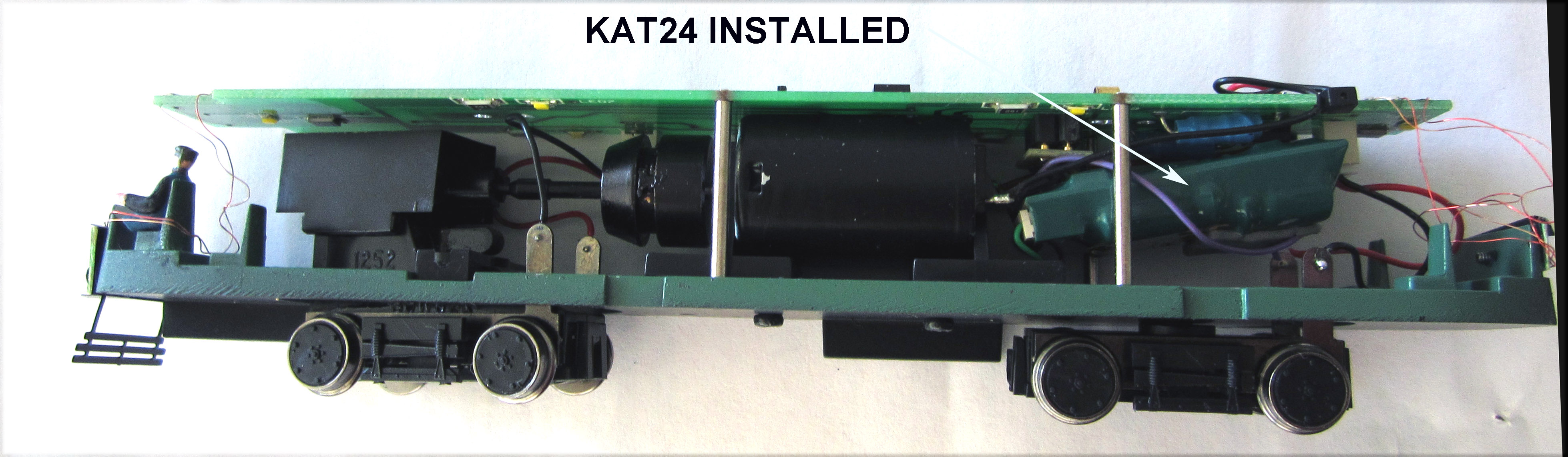
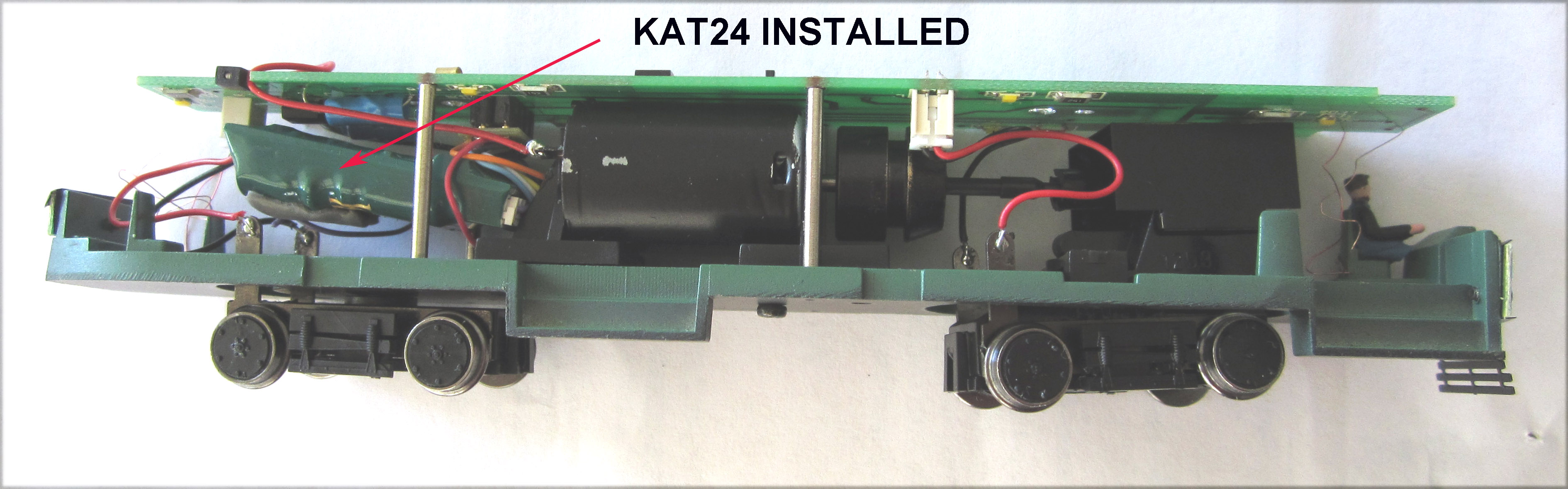
When available with the 2-pin plug, it is called the KA2-C, shown above left. We felt that the KA1 had more than enough capability for a trolley so we obtained one, courtesy of TCS, and installed it in a Bowser PCC car. This car, finished for San Francisco F-line PCC car 1052 became our test car. Southern California Traction Club modules have poles with span wires four inches from any interface point. Then then use bridge wire approximately 8" long between these spans. In one of those interfaces, we replaced the 8" wire with nylon fishing line. After the car was charged sufficiently, it ran through the fishing line with ease. We then ran the unit on some dirty overhead wire and it sailed right thought it without a single hesitation. The Southern California Traction Club (SCTC) discovered that found that the car equipped with the Keep Alive totally eliminated the dirty wire problem. So they recommend that each trolley modeler have at least one car equipped with a Keep Alive to clean wire prior to operating sessions. The major challenge will be finding the room to install the Keep Alive along with the original TCS decoder. For that reason, The SCTC did not even try to evaluate the KA2 device. The SCTC had been experimenting with the M4P-SH-KAC and the T4XP-SH-KAC decoders, equipped with the 8-pin NMRA plug, a short harness and a 2-pin plug for a Keep Alive, because these are applicable to the Bowser PCC cars. TCS has already taken the next step, integrating the Keep Alive capability into a decoder. We received our two test samples early last month. These are the KAT14 (SKU 1462) and the KAT24 (SKU1465). Both units are 1.31" x .65" x .29". The KAT14 has a Keep Alive capability of 2-5 seconds while the KAT24 is rated at 3 to 15 seconds. Once we received two T-1" (SKU1359) short harnesses with the required NMRA 8-pin plugs, the KAT14 was installed into John McWhirter's Bowser Los Angeles MTA PCC and the KAT24 was installed into George Huckaby's Bowser Detroit PCC. We still believe that the KAT14 as more than sufficient Keep Alive capacity for our trolley layout. But the installation into a Bowser PCC is not easy. It can be made to fit with a little persuasion. Without breaking any of the small wires to the rear brake lights, the decoder must be sort of "wedged" between the plug providing electrical connection to the rear truck and the base of the rear motor mount as shown in the next two photos:
For closer views, click here and here! We have spoken with John Forsythe of TCS and he is considering removing the JST plug that currently comes with the KAT14 and KAT24. This would remove 1/4" in length from the decoders. SCTC reported that initial testing of these decoders surpassed all of our expectations. Although we do not normally do this, we placed our car on the track without cleaning anything (wheels, trolley shoe, overhead wire) and it ran perfectly. Another great by-product of the TCS KAT14 and KAT24 is the slow smooth operation that you can now achieve with overhead wire power. We thought that the Bowser cars ran smooth before the TCS KAT14 & KAT24 decoders but performance took a quantum leap with them added. You will not believe it until you see it for yourself. Shown in the final photo are both DSRys 111 and LAMTA 3165 on the SCTC Club test track on May 17th during extensive test running.
These decoders may finally put an end to the erroneous perception of insurmountable problems with overhead wire operation in DCC. It just doesn't get any better than this right now. |
PCCII Streetcars Return to Philadelphia! The PCC-II streetcars, all built in 2004, finally returned to Route 15 on April 29th after a long interruption (October 2011) to repair track, long overdue for replacement.
SEPTA has lost completely the art of maintaining service on a surface rail line during routine trackwork. This should be no surprise since few of the current senior management seem to like surface rail transit anyway. The major change is that the cars go to the new Northern Liberties loop on the east end.
This new loop is marred by an incredibly stupidly designed junction at Frankford and Richmond. This junction has totally new track and special work but was designed and installed with non-clearance curves, appearing like it was designed by an 8-year old putting his Lionel Train set on the living room floor. In the next photo, PCCII 2327 is shown just after turning onto Richmond Street from Frankford Avenue. Note the orange NO CLEARANCE sign on the span wire and, if you look closely, the sloppy overhead wire construction, typical of current lackluster SEPTA efforts relating to this Route 15 line.
The PCC-II is the rejuvenated body of one of the 1948 PTC 2091-2200 series or the 1947 2701-2800 series PCC cars with a totally new LRV type propulsion and air-conditioning system added along with sealed windows. There were 18 cars built with the series 2320-2337 numbers assigned. The inside of the car has plastic panels and sealed windows sort of like an airliner. After a long battle with residents in West Philadelphia (sort of like the Los Angeles Expo line NIMBYs) along the 59th Street track which was to be used for cars leaving the Callowhill Depot, the line finally reopened to PCCII service in September 2005 after being a bus line since 1992. __________________________________________ The Custom Traxx Boston Air-Electric PCC cars - How to “housebreak” them! by Rich Allman, Bob Dietrich, Two of us, Rich and Brian, purchased a total of four of these fine models, which were offered by Custom Traxx beginning in March of this year. Brian obtained two of the version with the full fan monitor roof, and Rich got one with the full roof monitor and one with the original as-delivered Pullman Standard pole shroud and front air scoop. Rich found that to successfully navigate the 6 1/8 inch radius ORR switches, some filing of the cut out space for the power truck was necessary, which is an easy and anticipated modification with almost any Bowser traction drive. Rich found that for the car with the monitor roof, at least on his layout, a slightly shortened pole tracks better through the switch pans, another anticipated modification, at least for the idiosyncratic stuff on his layout. Brian has been successful with both of his cars using the as-delivered new Bowser 12600 PCC poles. He has equipped his cars for DCC. Brian has also equipped his two cars with HO scale Operational Automatic Traction Couplers [SCTC-40] and runs his cars as a two car train. Two or three car trains of these cars are what God intended, at least on Commonwealth Avenue, Beacon Street, and Riverside! Charlie helped Brian with an alternate floor mounting method. He anchored some long 4-40 screws into the threaded holes in the roof weights as shown in Figure 1.
He then cut off the screw heads and used a simple 4-40 nut above and below the floor for support. See Figures 2 and 3:
Rich chose another method to secure his shells to the floors, using Bob Dietrich's tried and true method of placing horizontal styrene struts above and below the floor on the sides as in older plastic locomotive models in order that the floors can be removed and replaced by gently spreading the sides of the bodies.
This is a great method of access to the drive if needed for work or lubrication. Rich also used a homemade pole bushing on the monitor roof car, which is a piece of tubing vertically soldered to a piece of PC board and pasted to the underside of the roof. A lead to the positive pole of the motor with a plug connection is soldered. He used an MTS pole bushing in the other car which is threaded and can be screwed to the inside of the shell connected to a circular contact, in turn with a plug-in connection to the plus lead on the motor. Initially, the pole sat a bit too deeply in the shroud and caused mischief on curves. This was easily remedied by cementing a small washer (00-90) to the top of the pole bushing. Obviously, the cars need to be wired for overhead operation, which can be half an evenings work for a pair or cars. All four cars had a problem not previously encountered with the Bowser drives. The cars would spin and not go forward, even with humongous amounts of weight applied. We tried the obvious. We ensured that (1) the track brakes were on correctly, (2) that the flangeways were clean, and (3) that paving did not push upward on the trucks. We tried removing the track brake assemblies just to be sure, but no luck. Initially, Charlie thought that there was either a problem with the nickel silver wheels or else too much spring pressure on the pole, causing the front truck to be slightly lifted from the rails, which turned out not to be the case, although Brians cars now have slightly less tightly sprung poles. He subsequently made an observation that the rest of us eventually also discovered. The wheels and axles on the rear trucks were not spinning freely and were causing a disabling drag on the power truck. This was frustrating to a huge degree until it was recognized, after which with some experimentation, the fix was easy, quick, and straightforward. Dismantling the truck, which is easy, revealed two things: First, there was a burr in the square bearing, (Bowser part 1257), on the inside that impeded the spin of the axle. This was easily cleaned out with a router as shown in Figure 5.
Second, there was burr on the inside of the axles that press fits into the sleeve, (Bowser part 1291), that holds the wheel half-axles sets together. This could cause gauge problems and potential derailments, which it did for Brians cars. Once this was recognized, it was easily fixed by sanding it off gently with a sanding wheel. After some lubrication of the wheel bearings and reassembly, the problem was resolved. Each car needs one ounce of weight under the floor just behind the power truck, especially for the 4% grades on Richs layout. All four cars now run flawlessly and are ready for detailing with paint and decals and windows and pole hook. Photos to follow when finished! The take-home lessons of this are to inspect everything systematically and that almost always an easy fix is out there. Also, the modeler should not be ashamed to ask for fresh eyes from someone else to analyze the problem and to not keep doing the same thing and expecting a different result - Einsteins definition of madness. We write this not to criticize either Bowser or Custom Traxx, but to offer a recipe for a very quick and reliable fix for a problem that once recognized, can be made to go away in a few minutes. None of us believes that any model can be taken out of the box and put on the tracks and expected to run without some tweaking. We hope this narrative will be useful to those whom we also hope will be many purchasers of these fine models! Incidentally Richard Allman and Bob Dietrich are past Presidents of East Penn Traction Club. Charlie Pitts, Tony Tieuli and Brian Ward are active members of Bay State Society of Model Engineers in Roslindale, MA. _________________________________________ |
|
Trolleyville
| Trolleyville Times | School
| Library
| Clubhouse
|
.gif) version of the map. There are two elevated stations on the line so far, sitting over a main cross street. The next photo is of the La Brea & Jefferson station.
version of the map. There are two elevated stations on the line so far, sitting over a main cross street. The next photo is of the La Brea & Jefferson station.