
|
|
| . |
| Return to the schoolhouse |
December 30, 1999
BACKGROUND
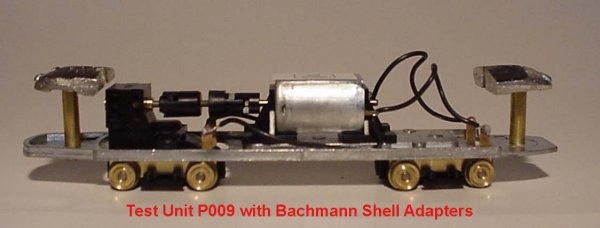
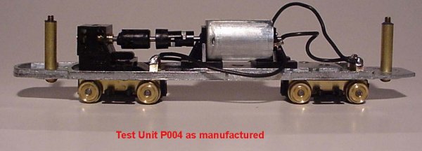
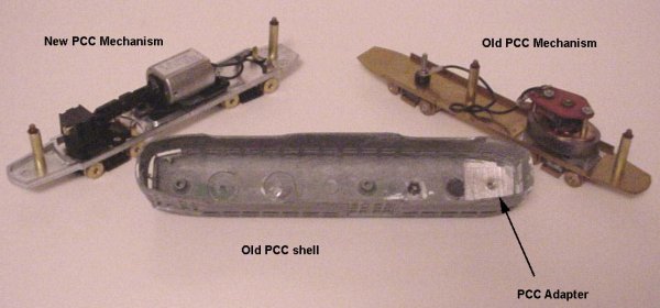
Since early December, Custom Traxx has been conducting a series of tests on the new Bowser trolley power units. Although we had the prototype gearbox and power truck since the National Train Show in August 1999, we did not get the complete PCC floors and trailing trucks until early this month. Lee English, of Bowser Manufacturing Inc., had been very receptive to our concerns and recommendations all through the development process. The first test units had the motors wired in reverse and Bowser corrected that in subsequent releases. The simple solution was to just unsolder the wires to the motor, unscrew the two mounting brackets flip the motor 180 degrees in the brackets and re-attach the brackets to the floor. Then the floor was found to have to have the trucks in incorrect locations (about one foot to far toward the rear of the car). All other dimensions seem to be right on. Both problems have now been corrected. Just after Christmas 1999, we received the first of the corrected revised floors and we began the process of removing the motors, trailing trucks and power trucks from the old floors and re-installing them on the new floors and beginning our evaluations.
1.Floor Modifications
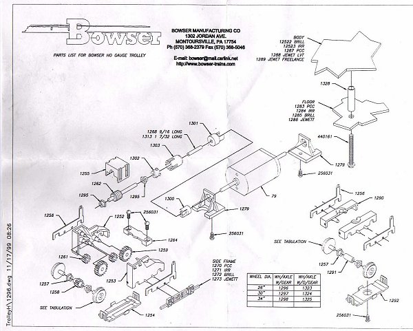
a. Separate the floor, part 1283, from both trucks by unsoldering the wires from the trucks, noting carefully from which side each wire is removed. The trailing truck is removed using the center screw and the power truck is removed using the two screws holding the bolster to the frame. To remove the power truck from the floor, it will be necessary to separate the power truck from the span bolster. It is a snap fitting so using a small screwdriver, pry up gently on the span bolster until it pops out of the assembly. The drive train components will usually stay together so they can be re-installed easily after this modification is completed.2. TRAILING TRUCK MODIFICATIONS
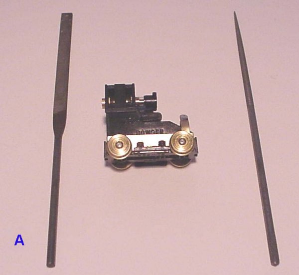
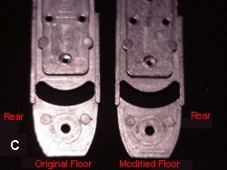
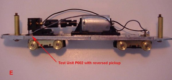
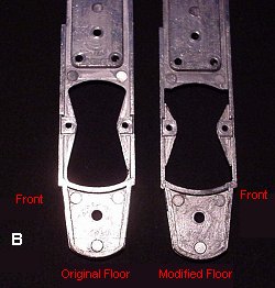
b. Using both a flat file and a round file as shown in photo A, file out the areas in the front and rear of the floor as indicated in photos B and C. This will allow for more truck swing and to reduce the possibility that the brass contact plates, parts 1256, will strike the sides of the floor casting. File the casting up to the sidewalls as shown. Do not file away any of the sidewall. The floor is electrically neutral, so our purpose is to prevent at least one, if not both, of the truck brass contact plates, part 1256, from contacting the floor during turns causing an electrical short. This is not a problem for those operating from overhead wires. During our modification evaluations, we actually reversed the parts 1256 on the power truck on one of the test units (P002) to see if that would prevent the shorting problem. It turned out not to be necessary to allow the unit to negotiate a six inch radius. P002 now powers a model of San Francisco Municipal Railway PCC 1061. The prototype car was Philadelphia 2116 until 1992.
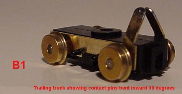
Note: While it is possible to bend the contact tabs on part 1256 without disassembling the truck, we found it better to do so to avoid breaking the retainers on the cover plate.
a. Carefully remove the cover plate, part 1292, by gently prying the slotted ends and remove both wheel sets. Although you will not need to do this, note that the trailing truck will be able to be split into the two halves, parts 1290.3. POWER TRUCK MODIFICATIONS
b. Remove the wheel assemblies, consisting of two wheel-axle sets, two bearings and a single collar that joins the two wheel-axle sets. The brass plates, part 1256, can now be removed. Using a vise, bend the tabs inward at least 45 degrees as shown in the photo B-1 of the trailing truck and reassemble the truck by replacing the brass contact plates, part 1256, the wheel-axle sets and the gear cover, part 1292. The truck can now be reattached to the floor using the single screw provided.
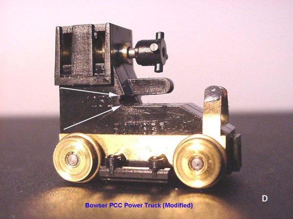
a. Carefully remove the cover plate, part 1254, by gently prying the slotted ends and remove both wheel sets. The power truck will now be held together by the top cover, part 1255. There is no reason for you to remove this cover and split the gearbox housings, parts 1252/1253.
b. Remove the wheel assemblies, consisting of two wheel-axle sets, two bearings and a single geared collar that joins the two wheel-axle sets. The brass plates, part 1256, can now be removed. Using a vise, bend the tabs at least 45 degrees and reassemble the truck by replacing the brass contact plates, part 1256, the wheel sets and the gear cover, part 1254.
c. Using a small flat file, remove some of the material on both sides of the gear box housings, parts 1252/1253 as shown in the photos. This will allow for more span bolster rotation.
d. Reassemble the span bolster to the gearbox housings and after positioning the drive components, refasten the span bolster to the power truck and then reattach the span bolster to the floor.
e. Resolder the motor leads to both the trailing and power trucks.
You should now have a PCC chassis that should negotiate a 6-inch radius curve. We tested two units on the Southern California Traction Club test track. As we mentioned earlier, we reversed part #1256 on the power truck of one of the test units. On this unit, shown in photo E, if both plates contacted the truck floor, there would be no electrical short as they would be the same polarity. As it turned out, neither unit developed any shorts on the 6-inch radius curve, as the contact plates do not seem to touch the floor after our modifications were made, so reversing part #1256 seems not to be necessary with the PCC chassis.