|  | . |
|
Return to the schoolhouse | Download in Microsoft Word Format |
||
Improved Lighting and Operation for the Bachmann Peter Witt Car
By Charles Long
|
||||||||
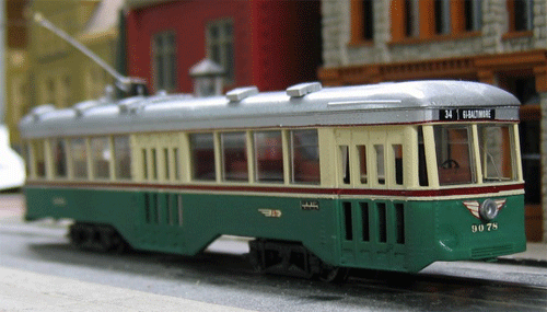
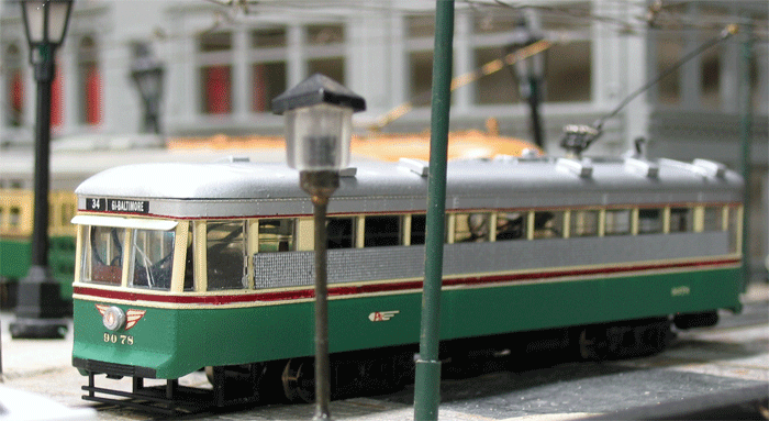
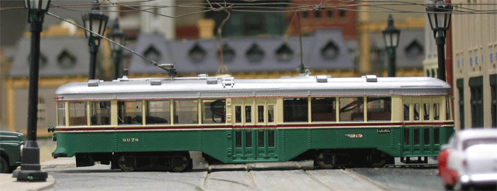
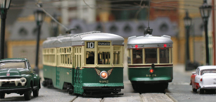
The HO scale Bachmann Peter Witt car was released in late 2007. Based on a Baltimore prototype, the car was made available undecorated and in Baltimore, Brooklyn, Chicago, Saint Louis & Los Angeles colors. The prototype car, 6119, resides at the Baltimore Streetcar Museum (BSM). It comes with the capability of both DC and DCC operation as well as installed lighting. All of the lighting is via small surface mount yellow LED’s. However a few things puzzled me. Operating with DCC using the supplied plug-in decoder, function 0 turns all of the lighting on and off, function 1 dims all of the lights including the interior. Furthermore, the center mounted rear taillight comes on in reverse and operates as a rear headlight. The rear tail marker lights mounted on the letterboard are dummies. Checking with John Engleman at BSM, he informed me that on car 6119 the headlight does not have a dimming function and is on a circuit with the destination sign and can be separately controlled from the interior lights. In addition the rear marker lights are battery powered and the center rear taillight displays “STOP” in red and is activated when there is pressure in the brake cylinder to stop the car. |
||||||||
|
||||||||
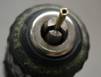
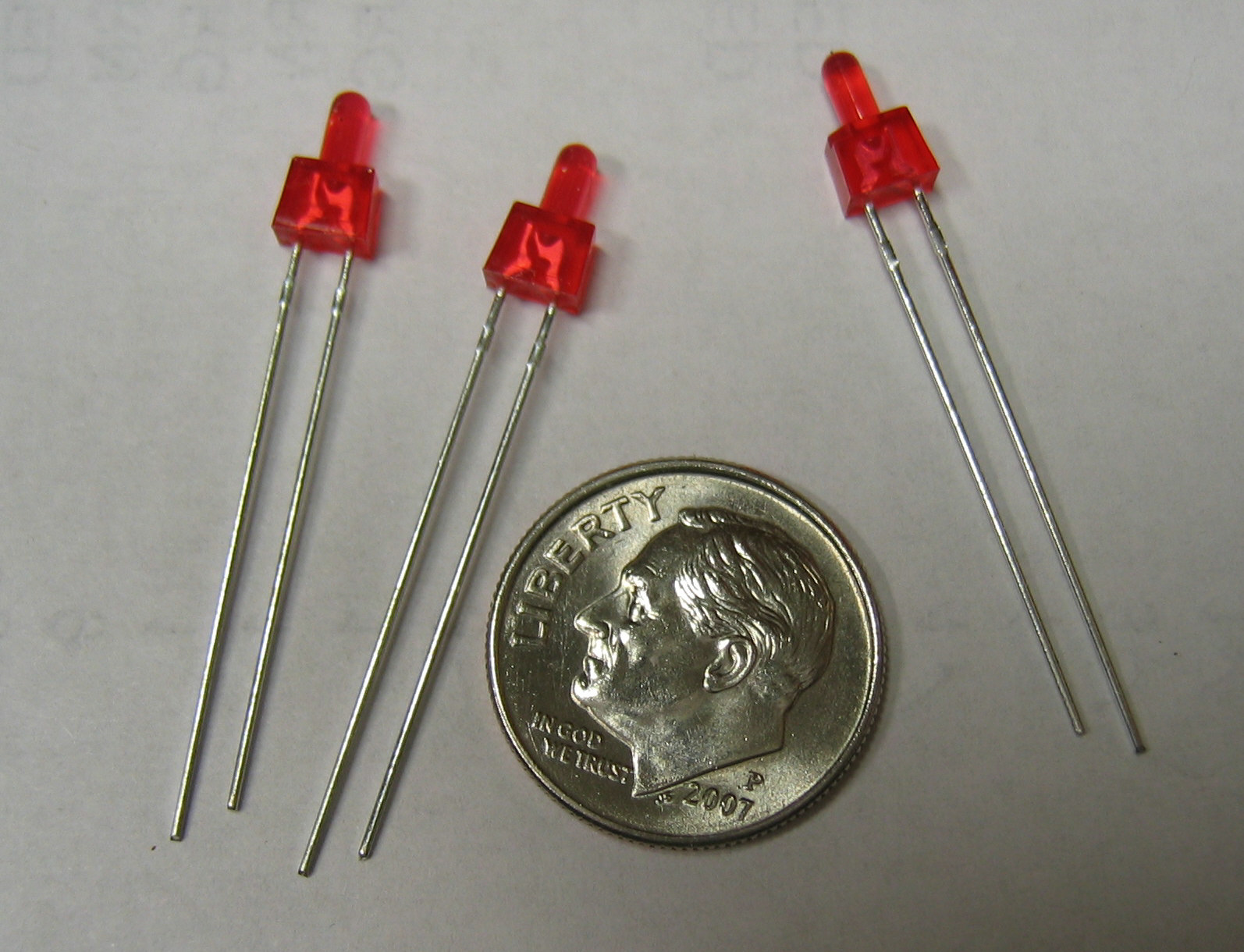
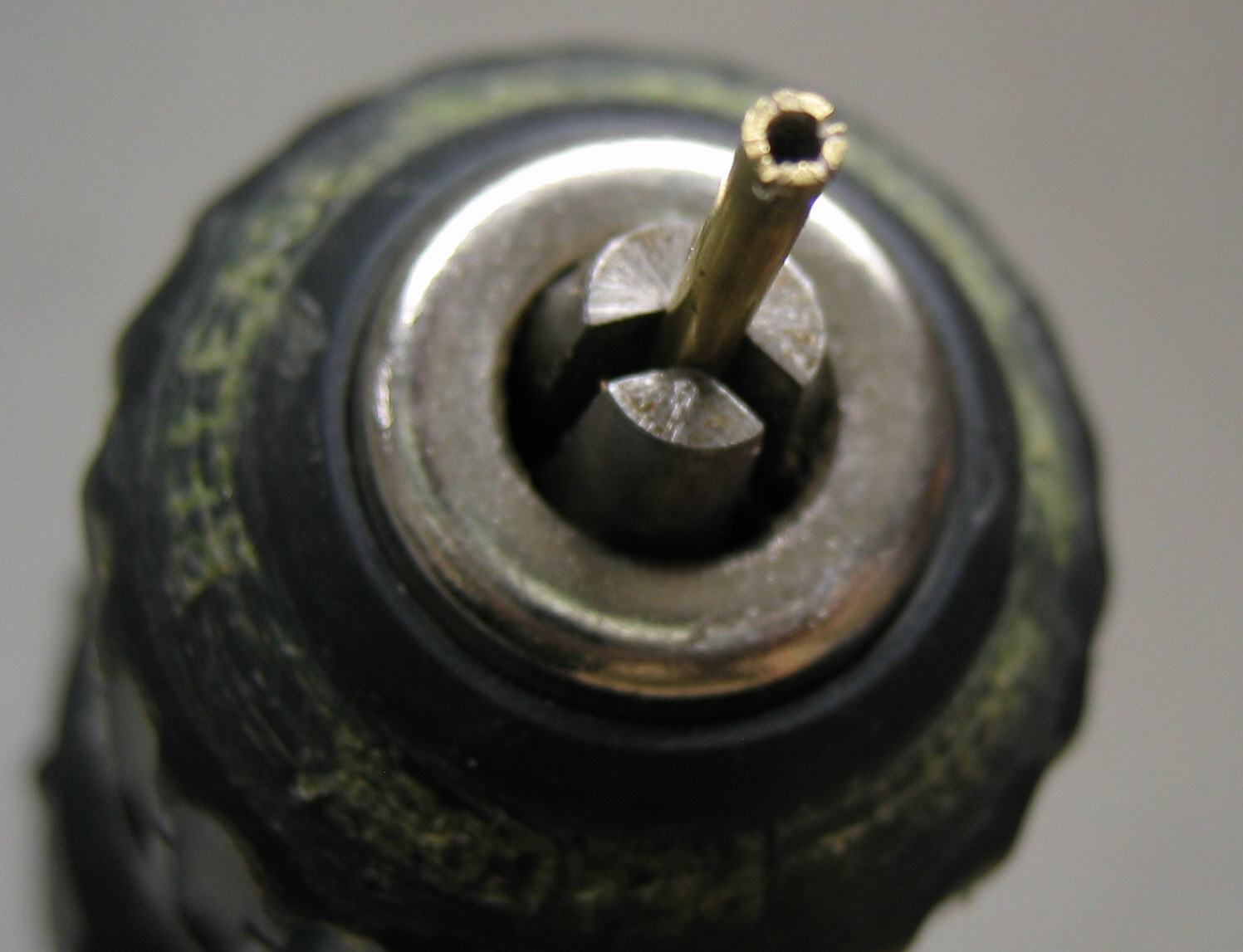
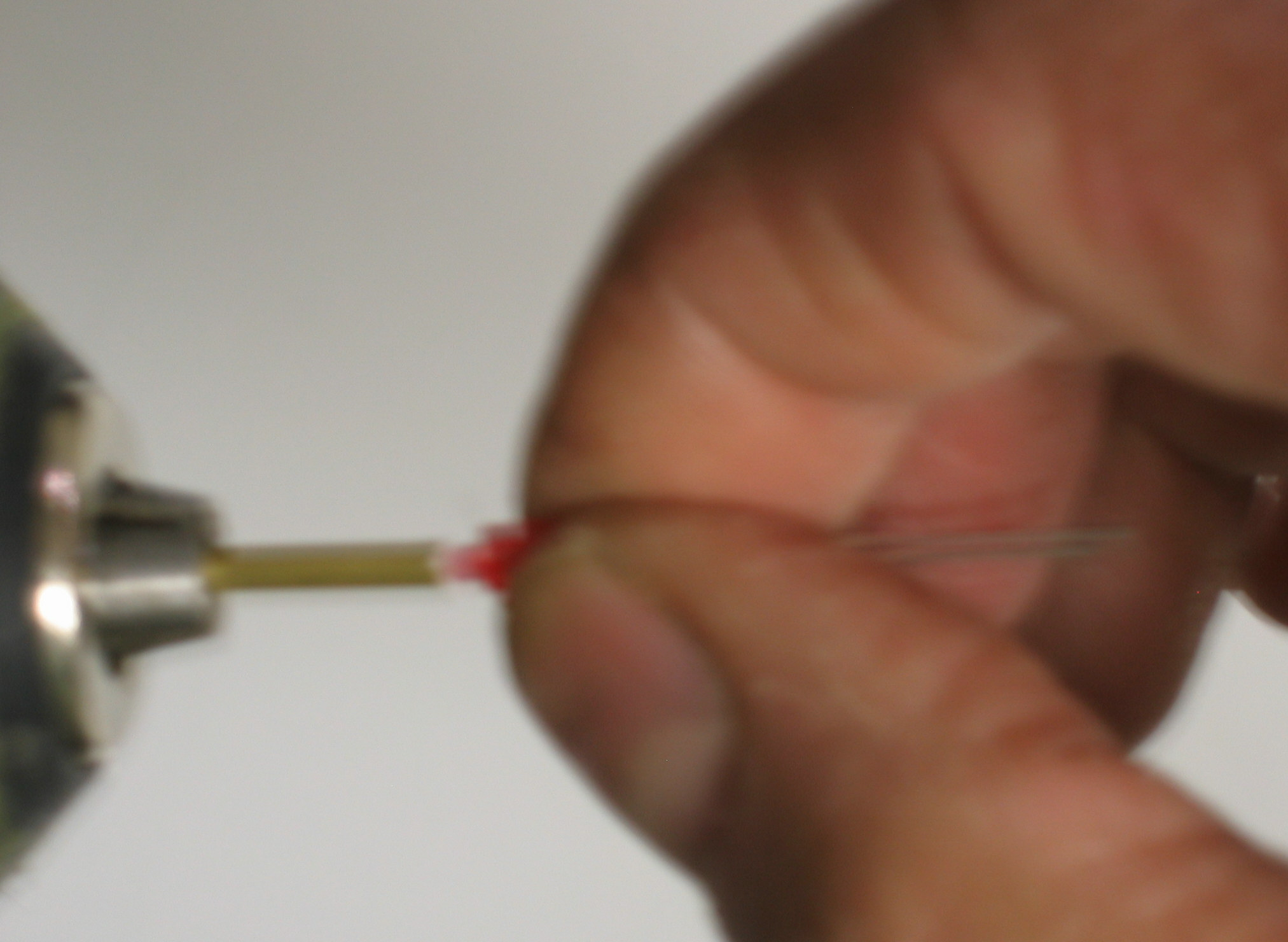
Although the Panasonic LED could be used for the center rear stop light, I was intrigued by the plastic light pipe arrangement used by Bachmann to channel light from the surface mounted LED on the circuit board. I obtained some surface mounted red LED’s (Digikey Part No. 160-1181-1-ND, ten for 83 cents) and tried my luck at replacing the factory installed amber rear LED with red. After temporarily removing the clear plastic light pipe I was successful. This is delicate, tricky soldering but most traction modelers should have the skills from working on overhead wire. The polarity must be correct, the LED should light when positive voltage is applied to L+ and negative voltage is applied to L2-. It is best to apply DC voltage to L+ and L2- and touch the LED to the pads to verify that it lights and is correctly oriented before soldering.
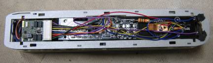
While the Bachmann model includes a DCC decoder, it is a basic one with minimal functionality. I substituted a Lenz Gold Series uninterruptible signal processing decoder with the optional Power-1 module that acts as an electronic flywheel.
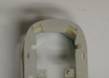
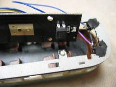
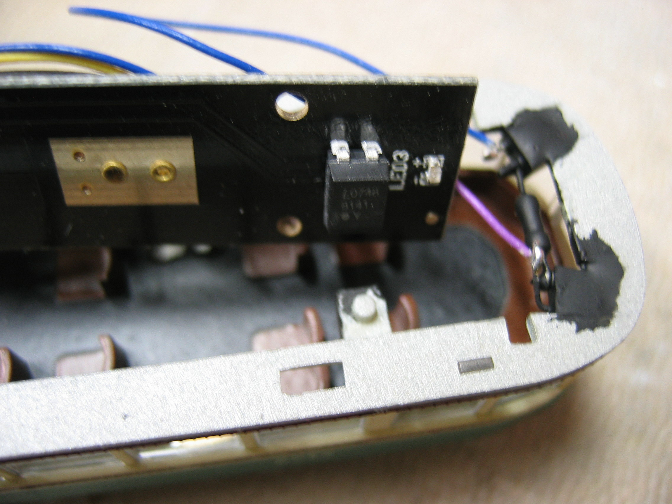
The Bachmann printed circuit board has two coils (L1, L2) and two capacitors (C3, C4) that filter the motor circuit to meet some of the European regulations. Reports are that they may cause problems with DCC and I removed them. I also removed diodes D1 through D5 that provide correct polarity to the lighting LED’s when used with standard DC. I then drilled four holes (#59 drill) in the rear of the board to mount the opto-isolator. Center it to clear the interior lighting LED-3 and the body mounting ears. The opto-isolator is mounted upside down hanging from the ceiling. The decoder wires are connected as follows to the header pins of the 8-position plug that connects with the socket from the lower floor printed circuit board:
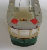
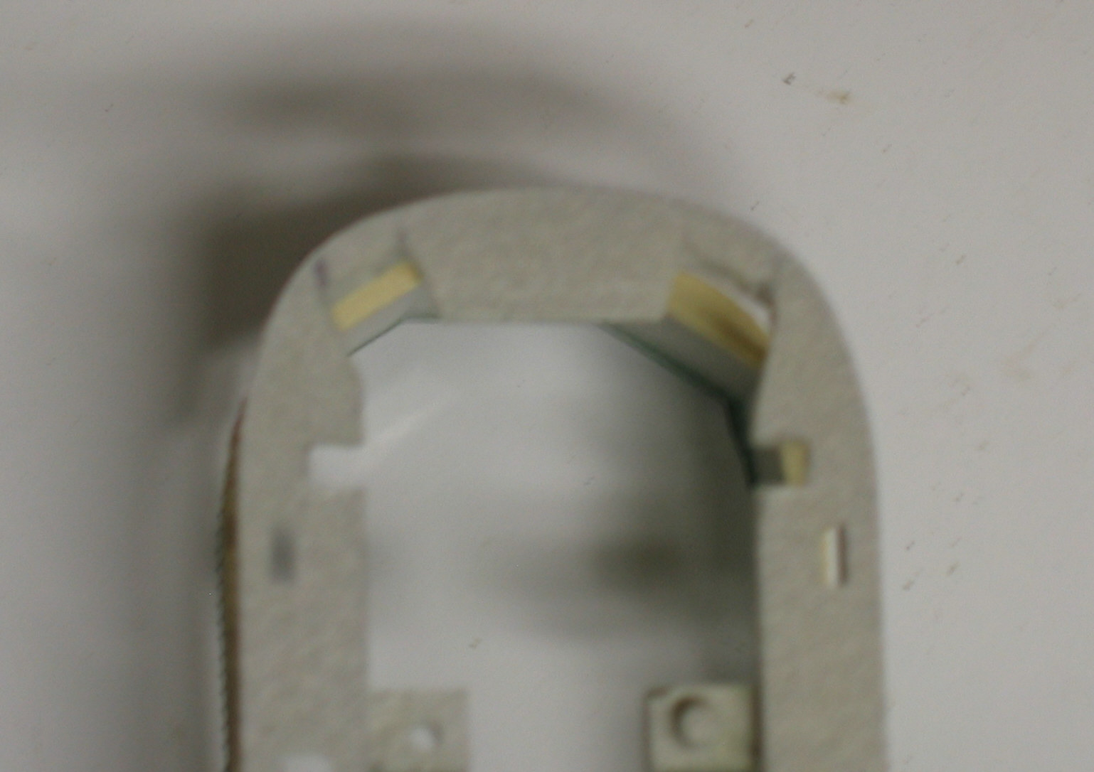
While the LED’s are great for markers and interior lights I still prefer to use incandescent bulbs for streetcar headlights to get the proper appearance. Bulbs rated at 1.5 volts develop little heat. I used a 1.5 volt, 30mA, 1.2mm clear bulb from Miniatronics along with a 390 ohm resistor to replace the front headlight LED and light pipe. Remove LED1, the surface mount resistor (R5) and the capacitor on the lower circuit board. I drilled a #55 hole through the floor centered from the headlight into the currently unused speaker cavity and used the speaker cavity for the 390 ohm resistor. The rear terminals of the removed surface mount resistor and capacitor were used for the lamp leads with the 390 ohm resistor in series with one lead. |
||||||||
The following configuration variable programming changes were made to the Lenz default settings: Please understand that all of the changes listed above are unauthorized modifications to the model that will probably invalidate the warranty. The Trolleyville times cannot and will not take responsibility for any models that get ruined in this process. Also, I wish to express my thanks to Bob Dietrich, also of the East Penn Traction Club, for a methodology to improve the turning radius (also described in Lesson 6-7 in the Trolleyville Schoolhouse). This method allowed the car to operate on my layout which has curves modeled on the PRT standard for city intersections, which spirals to a minimum radius of 33 scale feet.
|
||||||||
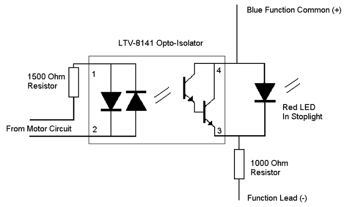
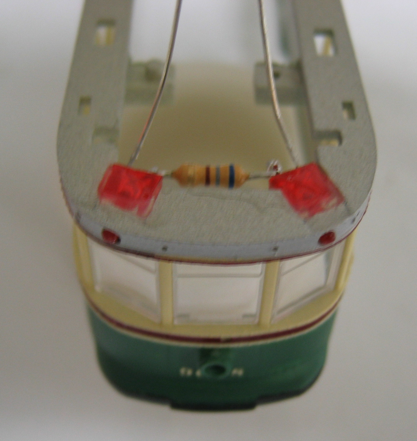
Although I firmly believe that the electronic flywheel action of the Lenz Gold series decoders and associated Power-I modules is worth the additional expenditure and the additional lighting functionality is a bonus, I understand that many may want to retain the original Bachmann decoders. In this case, I feel that a more simplified modification could be done. This would be retaining the yellow LED headlight, changing the rear light to a red LED and installing the opto-isolator circuit. While I added two rear marker lights at the letterboard using the existing mounting holes, they could be filled in and a single marker using the Panasonic LED with a 1000-1500 ohm resistor added. Furthermore, I believe the white and yellow function wires can be paralleled so that all lights will be controlled by function 0 and will remain on when the car is reversed.
2-15-2008 |

