WIRING HO SCALE TROLLEY CARS FOR
OVERHEAD DC WIRE OPERATION
by George Huckaby
February 15, 2002
Updated January 23, 2008
BACKGROUND
There are more than a few model trolley fans that love the challenge of erecting overhead wire, converting cars to run on overhead wire and enjoying the operation of it. In 1997, after two years of work, the Southern California Traction Club started to bring operational trolley modeling to the Great American Train Shows in California from San Jose to San Diego and by the year 2001 to even Las Vegas. The public reaction continues to be amazing. No one believes those cars are "...actually running from that little wire...". Most club members wish that they had a dollar for every question about whether the cars get their power from the overhead wire and twenty-five dollars for every time someone had to intentionally de-wire a car to prove it.
After converting over 250 cars to run on overhead wire and certify them for operation on the modules of the Southern California Traction Club, we always recommend that modelers do not erect overhead wire until they have throughly checked and tested their track in a two-rail opeartion first. After this is done and the overhead wire is erected, operate in the two-rail mode forst to chexk the tracking of the poles on the wire. With these actions satisfactorily completed, it is time for the first car to be rewired.
There are not too many parts that you need for rewiring a car. There are two general rules that we follow:
1. For every car with two trolley poles, we wire for "trolley pole" reverse. This allows cars to be reversed with just changing the poles and not changing the polarity of the layout. In trolley pole reverse, both brushes of the motor are wired to the two trolley poles and the trolley pole hooks supply the necessary connection to ground.
2. Every car is equipped with a connector so that the chassis and body can be separated for maintenance. Since the power will now come from the roof of the car, headlights are mounted on the body, and the motor is on the chassis, this only makes sense, especially if we will be running the cars for hours at a time. The list of parts for a normal double end car with two poles includes the following:
2 - SCTC -1 Trolley Pole Pivot Bushing;
2 - SCTC -2 Trolley Pole Roof Insulator;
2 - Miniatures by Eric HT-P1, HT-P2 or HT-P3 poles or other poles with 1mm pole base pivots;
1 - Miniatronics #50-001-02 2-pin connectors;
1 - Package Clover House #266 printed circuit ties; and
Two feet of flexible wire.
PROCEDURE
We are going to assume that most cars to be wired for overhead wire are equipped with can motors or has been so converted in accordance with another Trolleyville lesson. Many open frame motors have one brush grounded to the exterior of the motor. Neither brush can be grounded for "trolley pole" reverse wiring.
We are assuming also that both the body shell and the chassis are metallic and that the body shell has been removed from the shell and that we are ready for final wiring. The example that we will use is a Brooklyn Series 8000-8534 Double End Peter Witt as imported many years ago by Model Tramway.
Note: If the shell and/or the chassis is non-metallic. You will have to ground the trolley pole hooks to the wheels and use of a 3-pin Miniatronics connector. There are many different ways to do this but they depend on both the shell and the power unit to be used.
At any step in this procedure, you may find that there are space restrictions in completing a task. This is where ingenuity must be used. For starters, we have had to use such in repowering Suydam PERy cars such as 800, s and 950's with bulkheads separating open and closed areas, Ken Kidder brass double truck Birney Safety cars, Suydam Northern Electric 1010 box motors and Ken Kidder C & LE steel box motors. Anyway, for most of the other cars:
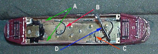
1. Cut two lengths of the Clover House #266 printed ties to fit the length of the main body of the car, excluding platforms or areas outside of the bulkheads. If you have single-sided printed circuit board and can cut it into strips, these are also useable. Sand one side of the printed circuit board lightly. Cement using ACC to the edge of the roof as close to the sides as possible. This position is chosen to avoid possible shell contact with the motor or flywheel in some low city streetcars such as double truck Birney safety cars. Note A in photo below,
2. Install the SCTC-2 roof bushing in the roof using the existing hole for the trolley pole. You may have to file out the hole just a little to accept the bushing. (In Bowser trolleys, the original Bowser insulator is cut off to be flush with the inside of the roof of the body shell.) Use a drop of ACC on the side of the insulator prior to insertion to hold the insulator in place.
3. Install the SCTC-1 trolley pole pivot inside of the insulator, using a drop of ACC on the side of the pivot bushing prior to insertion to hold the bushing in place. This will be helpful when the shell in inverted for the next step.
4. Using the male Miniatronics 50-001-02 connector, cut the wire three inches from the connector. Do not discard the remaining wire.
Note: At this time some conventions must be established.
a. The front of a single end car is obviously the front. The front of a double truck car is normally defined as the end with the powered wheels. In case of eight-wheel drive, choose one end as the front. Note the 'F' on the front platform to the right in the photo below.
b. With the shell turned upside down and the front toward you, the rear pole is to be soldered to the right printed circuit strip; the front pole is soldered to the left printed circuit strip. Use the remaining wire from the Miniatronics connector for this purpose.
5. Take a section of the white striped lead and strip 3/8" from one end. Tin the wire and bend into a circular shape with the same radius as the front trolley pole pivot. Wrap this tinned lead around the SCTC-1 pivot and using a flux, solder quickly to the base, avoiding melting the SCTC-2 insulator and being careful not to allow solder to enter or fill the hole of the pivot. Note B in photo below.
6. Using as little remaining wire as possible, cut to length, tin and solder to the right printed circuit board. To avoid fouling the motor, solder as far toward the rear of the printed circuit board as possible
7. Turn the shell so that the back is facing you and perform the same operation with the front trolley pole pivot. For this pole, use the other lead (the one with no white stripe). See item C in the above photo
8. Reposition the body shell so that the front is again toward you. Take the connector with the three inches of lead and solder the lead with the white stripe to the front of the right printed circuit strip and solder the other lead to the front of the left printed circuit strip. See D in the above photo.
|