|  | . |
|
Return to the schoolhouse | Download in Microsoft Word Format |
||
|
ORR TRACK -
PART TWO BASIC
INSTALLATION TECHNIQUES by George
Huckaby November 24, 2003 Revised May 22, 2007
1. BACKGROUND The
prerequisites for this lesson are the other Trolleyville lessons on
Prototypical Street Railway Track and ORR Street Railway Track - Part One.
Please review these two lessons very carefully prior to starting this one. We have found
that installation of this type of trackwork can be challenging depending on
your track plan. Complicated city intersections require patience. ORR STREET
RAILWAY TRACK, or ORR TRACK, as we will refer to it, is not designed for
two-rail operation but can be so adapted by skilled modelers. There are many
of you who, upon reading this lesson, or viewing the photos, will conclude that
you have used better techniques for this activity. We welcome your constructive
input to the Trolleyville Schoolhouse any time. We in NO WAY claim to be
experts at the installation of this ORR TRACK. But for the most part, our
trackwork, installed using these methods, is virtually derailment free. ORR TRACK
crossings and turnouts are castings and as such have the irregularities
associated with castings. Installation of ORR TRACK requires some modeling
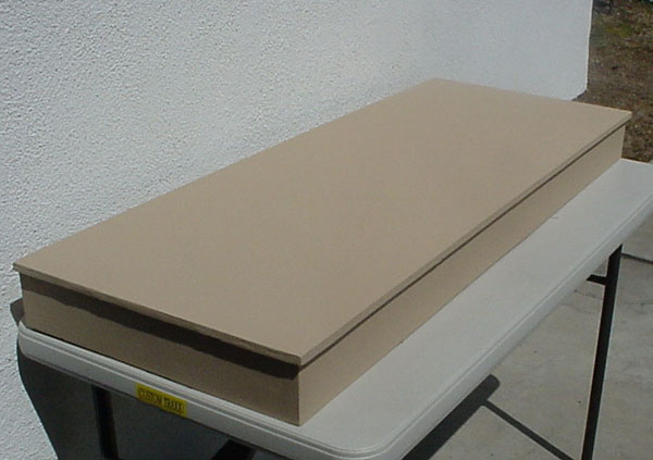
skills, particularly familiarity with the laying of track. 2. LAYOUT SURFACE PREPARATION For this
lesson, we documented the building of a Southern California Traction Club
module 941 during the last half of 2003. The module is 48" long by 18
3/8" wide. The benchwork of this module had been fabricated in 1994 and
trackwork had already been installed. Renewal of this module began on July 4,
2003 when all tracks originally on the module were removed. Any holes
previously drilled for switch tongues were all filled. It was then assured that
the homasote was glued to the benchwork and then at least one dozen drywall
screws were used to securely fasten the homasote to the benchwork. The module was then completely sanded and
painted as shown below:
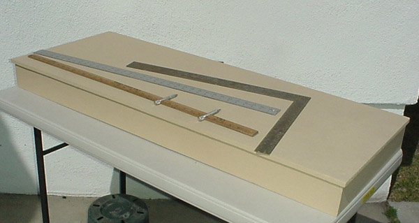
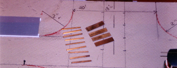
3. LAYING OUT THE PLAN The first step is to mark the track plan on the module using a pencil. Painting the entire surface makes marking the surface much easier. In this case, we will be using the track plan that contains an intersection similar to that used in several Philadelphia locations at one time. Since North and West Philadelphia is where I spent the 1950s' watching and riding trolleys, this is the basis for most of my modeling activity. Very few modelers ever have the actual engineering for these intersections at their disposal so we will create part of the intersection using the ORR TRACK specifications and part using some track information from the Philadelphia Rapid Transit. Mark the centerline of all tracks to be installed on the module. The tracks to which this module will be attached have 1.5-inch centers, although 2.0 inches is the currently accepted norm. The special work used by ORR TRACK, especially the right-curved (RC) and left-curved (LC) turnouts require a 1 3/8" double track spacing to ease installation.
Although double tracks in city streets were often close together, with inches of clearance between passing cars, planning for double track curves requires more planning and attention. Double track curves in city intersections were quite limited in the space that they had to work with. Accordingly many of these curves were "non-clearance" curves. Non-clearance curves are those where cars cannot pass each other without striking each other. Many cities had and still have non-clearance curves where cars cannot pass without striking each other. These were not originally non-clearance when the original small four-wheel equipment was used. To minimize this problem as cars grew longer and wider, most streetcars, including the PCC cars had tapered ends. For double track curves with radiuses of less than 12", tracks must be spaced much farther apart if the desire is to have "clearance" curves so that cars can pass without hitting each other. The amount of spacing depends on the length of the cars that you will operate and the radius of the curves that you employ on your layout. You will have to experiment with these factors in planning your layout. In this module, however, the center-line of the two tracks is 6
inches from the left edge or front of the module (another East Penn Traction
Club and Southern California Traction Club physical standard).
We also recommend that you select
your structures and sidewalks before laying any track. Consider that people
walked more frequently during the golden age of trolleys and that most
sidewalks in downtown areas were sometimes 10 to 12 feet wide. Note 1: For downtown
urban sidewalks, we use Smalltown USA
#699-7000 City Sidewalks along with others that are at least 10 feet
wide. Under the curb side of the sidewalk is affixed a strip of Evergreen #149,
.040" x .250", allowing .125" to extend past the end of the
sidewalk. The .040" strip will form the minimum depth of the asphalt
street, which will be paved with Durham's Water Putty. Place a strip of
Evergreen Strip Styrene #167, .080" x .156" under the opposite side
of the sidewalk, flush with the edge. This will give the sidewalk the correct
rake toward the street. We mention this here, as this will be evident in the
photos as the track installation takes place. Note
2: Although you will probably never build this particular intersection, the
tools and techniques described here can be used on the track plan of your
choice. Read carefully and note all the Notes!
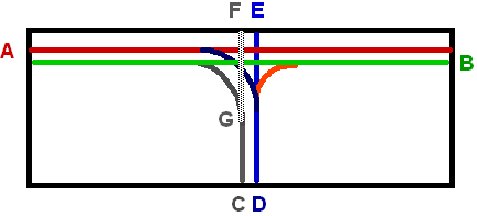
A sketch of the centerlines of the
track to be installed the entire is shown next. Installation of track FG will
require the careful fitting of three ORR TRACK crossings in a very confined
area and is considered an advanced project and will be discussed in the final
lesson.
This module
requires the following ORR TRACK items: 1 - Right Hand
Turnouts - Item 2400 - 2 PCs. 2 - Left Hand
Turnouts - Item 2403 - 2 PCs. 3 - Right Hand
Single Point -Mate - Item 2401 - 1 PC. 4 - Left Hand
Single Point Mate - Item 2404 - 1 PC. 5 - Right
Curved Crossing - Item 2420 - 1 PC. 6 - Left
Curved Crossing - Item 2523 - 1 PC. 7 - 90 degree
crossings - Item 2490 - 4 PCs. 8 - Girder
Rail - Item 2317 - One Bundle 9 - Clover
House 266 Printed Circuit Board Ties* - 5 packages 10 - Clover
House 276 Module Interface Ties - 2 packages *Clover House P.O.
Box Sebastopol,
CA (707)
823-7301 (Prefers written orders, letters and faxes. Write
for complete and well-illustrated catalog) 4. ITEMS TO CONSIDER BEFORE INSTALLING THE TRACK Note 3: Before
installing the track, it is important that the location of structures, trolley
line poles and sidewalks be considered. A trolley line pole in the middle of a
10-foot driveway will not look prototypical in that critical photo. Model
street railway equipment is much more limited in the size of curves that they
will traverse than prototype equipment. Many models will not operate over 6
1/8" curves and sidewalks at intersections are affected by these curves.
In the related lesson on Prototype Street Railway track, this problem is
discussed in greater detail. a.
The double track curve in this instance will be installed with 6 1/8"
radius curves to match the ORR TRACK turnouts and curved crossings. b.
Track spacing of double track will be made as close to the 1 3/8" centers
for which ORR TRACK curved crossings are designed. c.
Due to the fact that the ORR TRACK 2401 and 2404 Single Point Point-Mate
assemblies are now available, we will use one of each for the single track
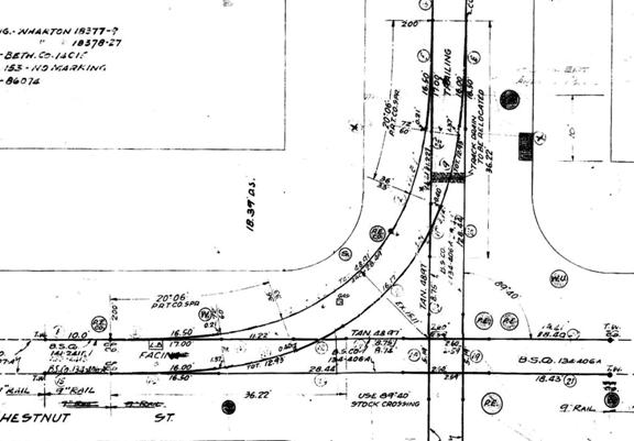
variable radius curve and we will use the PRT 9th & Chestnut
track plan as the basis for that curve. We enlarged the PRT plan to HO scale
and traced the track plan onto the module.
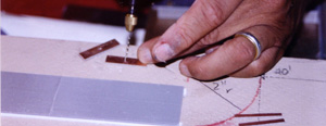
Since we are
using the ORR TRACK Single Point-Mate Assemblies, we will have to alter the
plan slightly. The radius of the points used on the prototype is 200 ft but the
ORR components are not that gradual, so we will have to move the Point Mate
assemblies further into the curve for a better alignment. See photo below. Note
4: As a general rule, short cars (those under 42 feet long) with truck
wheelbases under 6 feet and with power trucks using dual spring belt drives are
the best candidates to take sharp radius curves such as those we will be
installing on this module. Cars that we so far tested successfully on similar
curves on another module being constructed include Fairfield New Orleans 800
series cars, Brooklyn 8000 series Peter Witt cars, Pacific Traction San Diego
400-449 series cars, WP Car Chicago MU cars and Fairfield CSL 169 cars Note
5: As a second rule, heavier cars traverse sharp curves much better than the
lighter ones. We attempt to ensure that each 45' car weighs about 9 ounces
prior to operation. d. Some
tools that you should have on hand are: Dremel Tool with sanding and cutting
disks, High quality razor saw(s) for
cutting metal, High
quality soldering iron, preferably with adjustable temperature control, Electric
Drill with 1/2" drill bit, Vise,
and Normal
files, screwdrivers and tweezers. 4. LAYING
GIRDER RAIL TRACK (Straight) a. Preparing
the ties. Using Clover House 266 ties, cut each strip into seven 1.25"
sections, which equate to 9 ft in HO scale.
While it is possible to get 9 ties out of one strip, there will be
longer ties needed in certain places so keep the excess handy until the job is
getting close to completion. Note
6: Since we are making traction modules, there is a special need for very
secure rail attachments at the module interfaces. These rails are subject to
much stress during module set-up and damage in transit, as the rails must go to
the very edge of the module. Clover House now provides #276 Module Interface
Ties that are ideal for this purpose, as they are around 3/8" wide. They
are the only ties that are fastened with adhesive and a single track nail. The single track nail will allow us to
adjust rail height slightly at the interface should this be necessary later.
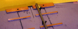
b. First we will place the ties at
the ends of the modules. These larger ties will have been drilled in the center
to accept a track nail, and placed at the ends of the module using the lines
that we have placed earlier. The use of the nail will allow us to make vertical
adjustments later should they be needed. Very thin shims may have to be placed
under the tie to match the height of the rail in the adjoining module, when
they are first attached.
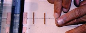
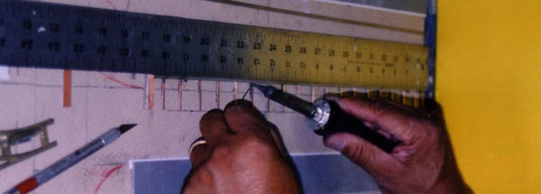
c. Along the marked track lines,
mark locations one inch apart for the ties and install the ties using the
following method: 1) Sand the bottom of
each tie to achieve a rough surface. 2) Apply glue
to the bottom of the tie and press into place perpendicular to the marked track
line. Ensure that 5/8" or 4.5
scale feet of the tie are on either side of the marked line. We have used both
ACC and Woodland Scenics Hob-E-Tac to secure the ties. When using other than
ACC, allow to dry for one hour before soldering track to these ties. As you
will see in many of the photos, considerable work has been completed on the
sidewalk installation and structure completion and location.
Note
7: Do not install any of the 9ft ties in the vicinity of any special work. Ties
for these areas will be cut later. We use the same remnant ties shown above at
the ends of the ORR TRACK Turnout and Crossings. This enables us to have a
solid soldered joint between the special work and any other special work or
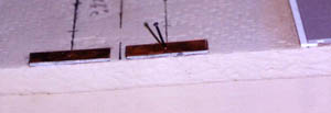
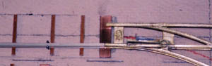
girder rail to be attached to it. 3) Track A from the edge
to the first right turnout will be the first track to be installed. The turnout
will be positioned and soldered in place using the Clover House Module
Interface Ties as shown below. A length of rail will be cut to fit between the
turnout and the edge of the module. This rail is nailed or spiked in the
correct position at the end of the layout and at the turnout and soldered in
place.
Note
8: Always leave about 1/32" of track protruding from the edge of the
module. This can be cut or filed later when modules are joined together for the
first time. . 4)
Using a straightedge, solder the rail to every other tie to distribute
heat. When you reach the end come back
to the opposite end and solder every other tie missed during the first pass.
5)
Now using track gauges, cut and fit the opposite rail, nail into place at the
ends and solder both to the module end plate and to the turnout. Note
9: ORR TRACK Girder rail when used on both rails requires very accurate gauge
between those rails. Wide gauge will cause as many derailment problems as
narrow gauge due to the flangeway. Curved track is especially prone to such
problems if not precisely installed. If gauging is a problem for you, you may
elect to use simple code 100 rail on the outer rail of any curve. But remember
the time saved here may be more than consumed when paving the street. Note
10: When working for extended periods, every fifteen minutes stop soldering and
allow all track recently worked to cool. When track is cool, check track gauge
before proceeding further. Correct any out of gauge problems before proceeding. 5. LAYING
GIRDER RAIL TRACK (Curved Track) a. Preparing and installing the ties. Cut and prepare
ties in the same manner done for straight track except that the ties should be
no farther than 1 inch apart and should be installed tangent to the center line
of the curve.
Note 11: This can be
the most challenging part of this entire effort. Girder Rail is asymmetrical
and requires a curving tool in order to bend it correctly. A limited number of
these tools are available from Custom Traxx (www.trolleyville.com). b.
Curving Girder Rail (Using the 2350 Curving Tool) 1) Read the instructions provided with
the #2350 curving tool, if provided. Follow the instructions that come with the
tool and use a strong vise to hold the tool while bending the girder rail. (We
bend entire 3-foot sections at one time, knowing we will use the leftovers some
time in the future.) 2) The tool consists of a 4"
by 3" base plate, two pairs of slightly dissimilar rollers, three shoulder
screws and three large washers, two 10lock washers, two 10-24 hex nuts and one
10-24 wing nut. You will need a 1/8" hex wrench for proper assembly. 3) Assembling the
Curving Tool a) Place a
shoulder screw into the top (not the tooled end) of an H roller. Put on a
washer and insert this into the left hole of the base plate. Put on a lock
washer and a hex nut and tighten. b) Repeat the
procedure with the other H roller in the right hole. c) Repeat
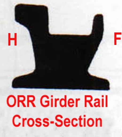
again, using an F roller in the slot and tighten slightly with the wing nut. 4) The Rollers
Note:
There are four rollers provided with the curving tool. Two rollers should be
marked F and two should be marked H. The H roller corresponds to the contour of the railHead side of the girder rail and the F roller corresponds to the contour of the Flangeway side of the girder rail as shown below:.
5) Curving the outer
rail of a curve a) Place two
"H" rollers in the fixed hole positions, using a shoulder screw, a
large washer, a lock washer and the 10-24 hex nuts. Place an "F" in
the slotted hole using a shoulder screw, a large washer, a lock washer and the
10-24 wing nut. b) Clamp the
curving tool in a vise, covering the wording "clamp in vise". c) Introduce a
length of girder rail from either side, passing it above the "H"
rollers and beneath the "F" roller with the railhead fully under the
"H" rollers and the base of the rail flat against the washers. d) Advance the
rail to a point just beyond the center roller and force its tooled slot down
against the rail flangeway, effecting a slight bend in the rail. Tighten the
center roller and slowly draw the rail through the curbing tool, both pushing
and pulling and keeping the rail fully under all three rollers at all times.
/fingers will not damage the rail but pliers may place unwanted dents and
scratches in it. e) The first
pass through the curving tool will put only a slight curve in the rail.
Additional passes will result in sharper and sharper curves. Before each pass
with the girder rail, loosen the center roller, move in down about 1/16"
and retighten before use. The arcs on the plate are approximately 1/16"
apart f) When the
rail is first introduced, it will easily fit under the outside and center
rollers but must be forced with fingers or a wooden stick up under the third
roller. Push and pull the rail through
the rollers and repeat this procedure until the desire curve is obtained. 6) Curving the inner rail of a curve a) Place two
"F" rollers in the fixed hole positions, using a shoulder screw, a
large washer, a lock washer and the 10-24 hex nuts. Place an "H" in
the slotted hole using a shoulder screw, a large washer, a lock washer and the
10-24 wing nut. b) Clamp the
curving tool in a vise, covering the wording "clamp in vise". c) Introduce a
length of girder rail from either side, passing it above the "F"
rollers and beneath the "H" roller with the railhead fully under the
"F" rollers and the base of the rail flat against the washers. d) Advance the
rail to a point just beyond the center roller and force its tooled slot down
against the rail flangeway, effecting a slight bend in the rail. Tighten the
center roller and slowly draw the rail through the curbing tool, both pushing
and pulling and keeping the rail fully under all three rollers at all times.
/fingers will not damage the rail but pliers may place unwanted dents and
scratches in it. e) The first
pass through the curving tool will put only a slight curve in the rail.
Additional passes will result in sharper and sharper curves. Before each pass
with the girder rail, loosen the center roller, move in down about 1/16"
and retighten before use. The arcs on the plate are approximately 1/16"
apart f) When the
rail is first introduced, it will easily fit under the outside and center
rollers but must be forced with fingers or a wooden stick up under the third
roller. Push and pull the rail through
the rollers and repeat this procedure until the desire curve is obtained. c.
Installing Curved Girder Rail Note
14: When installing curved girder rail, it is best to have all the printed
circuit ties fastened to the homasote and the center line of the curve clearly marked
on the layout surface. 1) If this
curve is to begin and end with specialwork, ensure that both specialwork pieces
are firmly in place before installing the curve. 2) Ensure that
printed circuit ties are firmly installed at least every inch of the curve. 3) Ensure that
the centerline of the curve is clearly marked. 4) Carefully
measure the curved rail section and install the inner rail for fit only. 5) Spike the
rail temporarily in place and check carefully for alignment. When alignment is
found to be correct, solder rail to the ties one at a time and to the adjoining
rails. 6) Now cut and
fit the outer rail. When the fit appears correct, check track gauge and if all
measurements are correct, then begin to install and solder the outer track in place.
Check track gauge continuously and do not proceed unless gauge is maintained
accurately. Miscalculations today are derailments tomorrow. 6. TURNOUT
AND POINT-MATE INSTALLATION Turnouts must
be precisely located due to the holes that must be drilled in the homasote to
accommodate the vertical throw rod. a. Using a
one-inch piece of brass tubing, place over the switch tongue throw rod, except
for the 1/16" closest to the bottom of the tongue. Solder the brass to the
cast rod. Note: Not leaving the final 1/16" clear may cause the tongue not
to close fully. This is always the
first step followed with any of the ORR TRACK #2400 through #2404 items, b. Using some
of the #276 Module Interface Ties (refer to paragraph 4a and note 6 immediately
below that paragraph), place these ties at the three interfaces of each turnout
as shown in the next photograph. This will provide a solid point at which to
join and solder to the next rail.
Note
15: A significant portion of this track installation and module detailing has
been performed at Great American Train Shows during scheduled workshops. The
Southern California Traction club and Custom Traxx believes that the
inconvenience of performing these tasks outside of the comfort and exclusivity
of the shop situation is more than compensated by the appreciation of the
general public. 7. CONCLUSIONS At this time, you have been presented
with the techniques and tools that we have been using to install ORR
TRACK. There are probably many other
methods that are being used by other traction modelers. If they were willing to
share these items with us, we would gladly add these to the article and/or
feature these items in the Trolleyville Times. But we need to hear from you
other modelers. Now on to part three for an interesting intersection. |