|  | . |
|
Return to the schoolhouse | Download in Microsoft Word Format |
||
|
ORR STREET
RAILWAY TRACK - PART ONE THE PRODUCT
LINE by George
Huckaby November 20,
2003 1. BACKGROUND
Most long-time
HO scale traction enthusiasts are familiar with ORR Custom Track Components.
This 15-year-old product line consists of streetcar girder rail single-point
turnouts, crossings and girder rail that were developed and produced by Richard
Orr of Omaha, Nebraska. After many years of personally casting these items,
Richard transferred the business to Custom Traxx in June 2003, and Custom Traxx
renamed the items ORR STREET RAILWAY TRACK and added catalog numbers. This
track enables the traction modeler to recreate the city scenes with track so
prevalent in the United States and Canada until after World War II. Using ORR
STREET RAILWAY TRACK, or ORR TRACK, as we shall refer to it, will be presented
in three parts: In this part,
we will discuss layout planning in general and the ORR TRACK, as it will be
made available by Custom Traxx beginning in 2004. In Part Two,
we will show how to lay the track for simple installations, including some
turnouts. In Part Three,
we will show how to fabricate intersections using turnouts and crossings and
some techniques to be used for more complicated specialwork. Before
starting to install any of the ORR TRACK, it is suggested that the modeler
review the lesson on Prototype Street Railway track, Lesson 2-2, contained in
the Trolleyville Schoolhouse. 2. SOME
FACTS ABOUT ORR STREET RAILWAY TRACK a. ALL ORR
TRACK consists of simulated "girder" type rail streetcar track, which
are compatible with code 100 "T" rail. Except for the 3-foot long straight girder rail sections, all
other trackwork is cast from White Tombasil, bead blasted and chemically
treated. b. ORR
Right-Hand (RH) and Left-Hand (LH) Switches and the Right Curved (RC) and Left
Curved (LC) crossings contain curves of 6 1/8" radius. c. ORR RC
(right curved) crossings are intended for use with the RH turnouts crossing
double trackage with 1 3/8" centers. Approximately 3/4" of the inner
rail of the turnout must be removed to fit the crossing into the correct
location. ORR LC (left curved)
crossings are intended for use with the LH turnouts crossing double tracks with
1 3/8" centers. Approximately 3/4" of the inner rail of the turnout
must be removed to fit the crossing into the correct location. 3. PLANNING THE LAYOUT - Before
starting this project, a precise track plan is required. This plan should be
drawn out carefully in full size and examined carefully to ensure that the
results will be what is desired.
Provided is this lesson are templates of each of the turnouts, crossings
and point-mate assemblies that currently comprise the ORR TRACK line: a. COMPLETE
TURNOUTS (3):
b. CURVED CROSSINGS (2):
c.
STRAIGHT CROSSINGS (5): d.
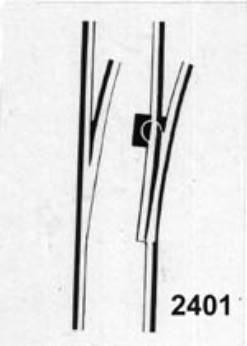
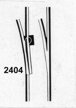
SINGLE POINT-MATE ASSEMBLIES (2):
The 2401 and
2404 Point-Mate Assemblies had not been available for some time and are
extremely useful for non-standard curves and crossovers. They are now again
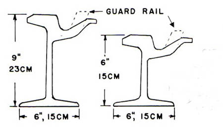
available. e. STRAIGHT GIRDER RAIL - Prototype U.S. girder rail has
cross section shown below. It still can be found in Philadelphia, San
Francisco, Toronto and many grade crossings on minor streets in Southern
California even though street railways vanished there over 40 years ago. For
curves and special work such as turnouts and crossings, a modified version of
girder rail is used. Normally called girder rail with extended flangeway, we
will just refer to it as Girder "High-Guard" rail. Note that the flangeway extends higher than
the top of the railhead. When this rail
is used on curves, the back of the flange of the wheel on the inside rail
actually contacts this guardrail. Use of this Girder "High-Guard"
rail prevents the flanges on the outer wheels on a curve from
"picking" rail joints or frog points and causing derailments. The
backside of a single point turnout acts as a section of Girder
"High-Guard" rail by forcing the opposite wheel into the curved route
of the pointless mate opposite the movable tongue of the turnout.
Note the web
or dept of girder rail. This rail is
actually a modified I-beam but, while extremely difficult to work with in the
prototype, it had the ability to carry streetcars without flexing under their
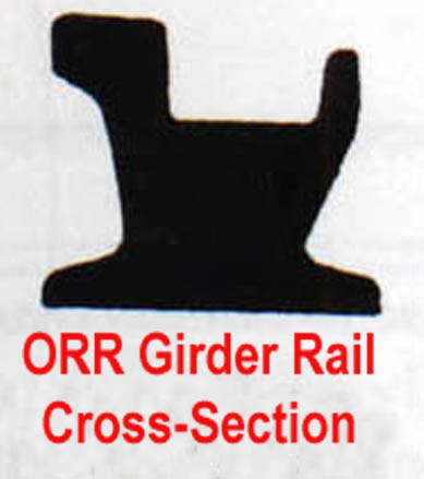
weight, thus ruining city pavement. Simulated girder
rail is available in 36" or meter length sections. This rail is code 100
in size with the cross section shown in the next illustration. Girder
"High-Guard" rail is not currently available for many reasons but the
major reason is the different size and oversize flanges used in various HO
traction models produced over the years.
The difference
in cross section is due to the oversize flanges currently used in HO scale and
to have sufficient strength in the web for model track. Now that you are aware of the items that are available, and still wish to model street railway track, please proceed to ORR TRACK PART TWO. |